I recently made my first foray in learning probably one of the most advanced Blender add-ons that exists: Animation Nodes (AN onwards). And by 'learning' I mean I've done one project in it and don't know when I'll do another.
Here is my first, and possibly last, test:
Now I have the rather unenvious task of trying to explain how I did it. Because I said I would and it seemed like a good idea at the time and now it's two thousand and ninety-three words later and I've come back up to the top of this post to write about how long it's taken and how I regret saying I would explain it.
However, despite the time it's taken to write this, this isn't a step-by-step tutorial and will probably take some investigation of your own to get a similar result. I merely nudge you towards the door, you must stumble your own way through it.
There are 3 main parts to re-creating the effect:
- Filling an object with other objects.
- Scaling the objects with AN.
- Creating the 'wave' effect with AN.
When I first started this mini-project I wasn't even intending to use AN, I was just trying to see if it were possible to fill an object with lots of other objects. It was only after looking at the sphere-filled torus that I wondered if I could animate it nicely.
My point is, at least in this version, the generating of the spheres to fill the torus was done beforehand. I would eventually like to try doing this step more procedurally as well, but for now this is a much more manual process.
Now, if you are ready to have some learning flung at you, proceed to the first part.
The Filling The Torus With Spheres Part
I'm not going to go into mega-detail for this part (or indeed any part), but the basic process is to fill a torus with a particle system of spheres and then use a rigid body system to allow the spheres to settle into non-intersecting positions:
- Fill an object with particles by using an 'Emitter' type particle system set to volume and a sphere as the Dupli Object (with particles set to start and end on frame 1).
- Convert the particle system to separate objects (Ctrl + A > Make duplicates real), make them all single users (U > Object & Data) and apply rotations and scales (Ctrl + A again).
- Set the new spheres to rigid bodies.
- Make the torus a passive rigid body set to Mesh and flip its normals so the rigid body system knows you your intention is for the rigid bodies to collide with the inside of the mesh.
- Turn off gravity (set gravity values to '0' in the Scene tab in the Properties Editor) and run the simulation.
- Discard any spheres that escaped the torus. They are dead to us now.
- On a frame where the spheres have settled, select all spheres and apply the Visual Transform (Ctrl + A > Visual Transform). This sets the spheres' positions to their positions as calculated by the rigid body simulation.
- Remove the rigid body settings from the spheres.
After doing this project I actually found someone had already done nearly the exact same steps (explained in far more detail) in their own YouTube tutorial here.
The First Animation Nodes Part
This is the part where the real 'fun' begins:
When I first made this it wasn't immediately obvious where to start. Partly, that's because with AN, nothing is obvious, immediately or indeed ever. Nevertheless, I had heard enough about AN to know that 'Subprograms' might lead me to the effect I wanted. So there too, is where we will begin.
Here is the first section of AN node setup, which deals with scaling the objects:
A key concept of Animation Nodes is to think about repeatable chunks of work. Instead of having to animate each object individually, we create a chunk of work (or in AN terms, a 'Subprogram') that takes in one object and animates it. We can then take that chunk of work and repeat it for as many objects as we need.
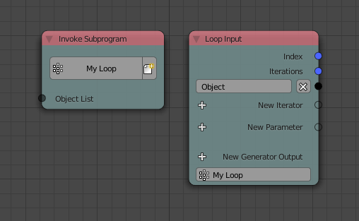
The 'Loop Input' node is connected to the chunk of work and the 'Invoke Subprogram' node calls that chunk of work as many times as needed.
How does the 'Invoke Subrogram' node know how many times to run the 'Subprogram'? Well, that's what we'll set up first.
After adding an 'Invoke Subprogram' node and choosing 'New Subprogram'> Loop, we need to change the 'Loop Input' node to accept a different input. Ideally, we need it to take in a list of objects and perform an operation on each one. Luckily, that's as easy as clicking the 'New Iterator' button on the node and choosing 'Object List' from the list of available inputs.
You'll now see that the 'Invoke Subprogram' node has changed its input from being 'Iterations' to 'Object List'. Far more useful. The 'Loop Input' node now knows that I will be passing it a list of objects and that I want to run the 'Subprogram' for as many objects in the list.
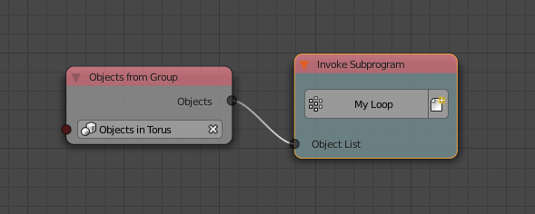
As for the list of objects, we can do this with a regular Blender object group, so add all your spheres, or whatever confounded shape you've used, add them to a group (Ctrl+G) and name it something completely irrelevant, like 'Group.001'. You know, something that will be completely unintelligible when you come back to this project in a few months. I've been silly and named my group 'Objects in Torus', which almost sounds like a useful name. I'll change it later.
So to summarise, the 'Invoke Subprogram' node will be passed a group of objects and it's going to loop through the list of objects and animate them depending on what is connected to the 'Loop Input' node.
Add an 'Objects from Group' node, choose the group in the node's drop-down list that you just created and then connect its one output to the 'Subprogram's one input, like so:
That unnerving, unusual feeling, which you're hopefully feeling if my writing has served its purpose, is the feeling of starting to understand something, of making progress. A quite unusual feeling when first working with AN. Make the most of it, because it probably won't last long.
Now we're onto the actual animation, we want to be able to pull an individual object from that list. We already set up the iterator, and when we did this the 'Loop Input' node got a new output called 'Object'. We can now add any nodes we want to animate that individual object and the animation will get applied to all objects in our group, because the 'Object' output changes to a different object in the group each time the 'Subprogram' runs.
Here are the nodes, connected to the 'Loop Input' node that will actually animate each individual object:
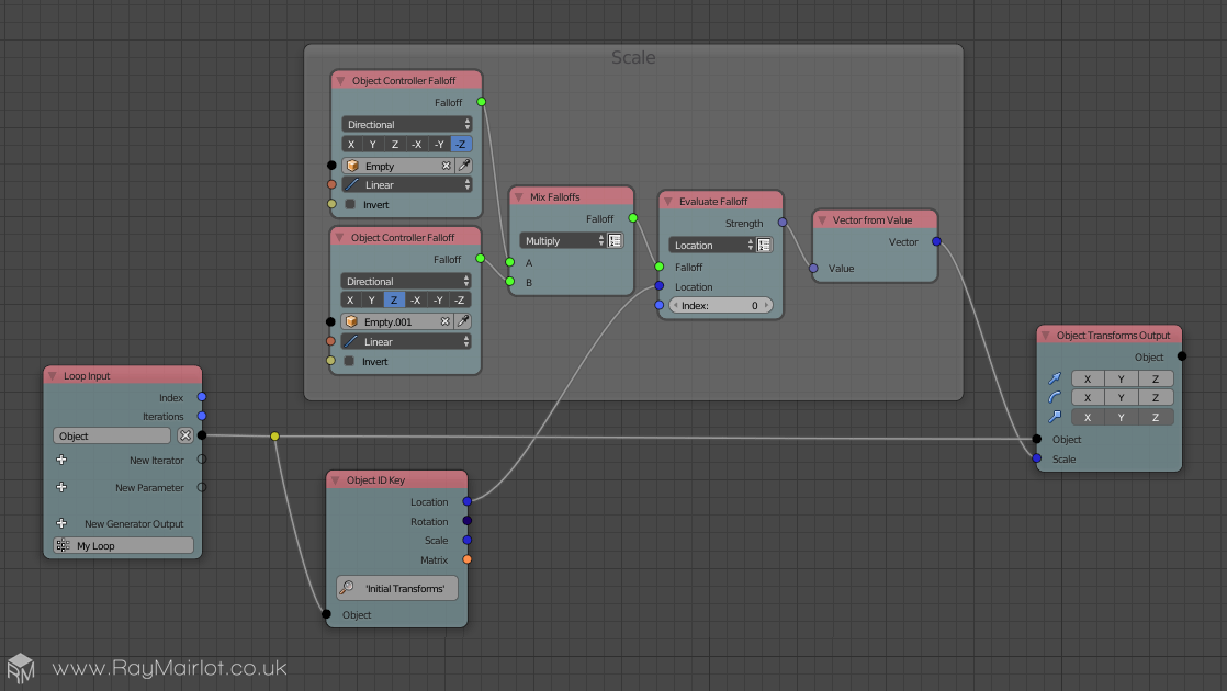
The basic idea of how it's animating the object is it is looking at the location of two empties (one either side of the torus) and depending on how close the empties are to the individual object, it should be scaled somewhere between 0 and its original size. The empties are then animated closer and further away from the object which means the objects will then individually scale up or down.
To summarise the node setup above:
- Read in the 'Falloff' (a bit like Blender force fields, where there is an area around an empty in which objects are effected) - in this case we're specifically looking at the 'z' or '-z' direction of each empty and adding them together (so that both falloffs are considered). I think the falloff range is 0-1 so multiplying them together actually works better than adding so that the maximum values will never exceed 1 (1 x 1 = 1, obvs).
- Use the 'Evaluate Falloff' node to compare the current object's location and its distance to each of the empties (each object is only ever in range of one empty).
- Use the output of this calculation as the scale value for the object. As the objects have their scale applied, when the falloff is 1 the objects will be at full size, otherwise they will be scaled down.
On the left in the screenshot below, you can see the two empties selected, whose falloffs are compared to each object's location:
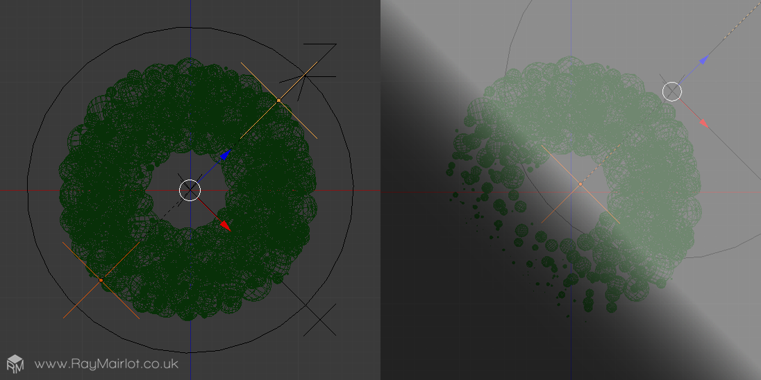
They're parented to a larger empty which is animated diagonally along the local 'z' axis as shown above. This is how the effect happens diagonally, as the 'Object Controller Falloff' nodes are set to read the local 'z' and '-z' axis respectively.
You can see on the right (above) a representation of the falloff, where in the centre it's lighter and the objects are full size, but if the empties move diagonally up and right, the imaginary dark falloff area will also move, start to cover the torus and cause the spheres to scale down.
Creating the 'Wave' Effect
The third and thankfully final part (come on, we're nearly at the end now) is to create the billowing wave effect. Here's the node network for the wave effect (I've removed the nodes that handle the scaling for the minute, just to make things a bit simpler):
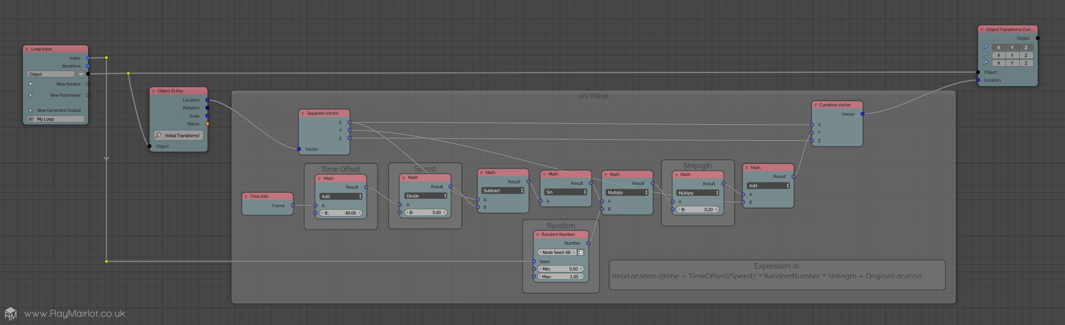
The basic idea is that we are taking the original location of the object and using a 'sin' wave to animate it back and forth on the 'y' axis, adding in a bit of randomness for good measure along the way. The node setup above equates to this equation:
sin(xLocation - ((time + TimeOffset)/Speed)) * RandomNumber * Strength + OriginalLocation
For those that don't know, the 'sin' function produces a wave depending on the number fed to it. Seeing as we want an animated wave we need to pass in a constantly changing value, so we pass in the time value ('Time Info' node), offset it just so the wave starts on the frame I want (the 'Math' node adding 40 to offset by 40 frames), turn down the effect a bit ('Math' node dividing by 5) and finally we subtract the object's original 'x' location so that each object gets a slightly offset sin value (otherwise they would all move the same amount).
After that we multiply in a bit of randomness between 0.5 and 1 so they each move a bit more individually, turn down the overall effect by multiplying by a number less than one, add it to the original 'y' value (so they start from their original 'y' positions), combine the 'y' location with the original 'x' and 'z' locations, before it's finally used by the 'Object Transforms Output' node which sets the location for the current object. Phew.
It's possible, likely even, that this equation could be simplified, but such was the joy of finally getting something which resembled a result that I couldn't bear to touch anything and accidentally break it.
Add it all together
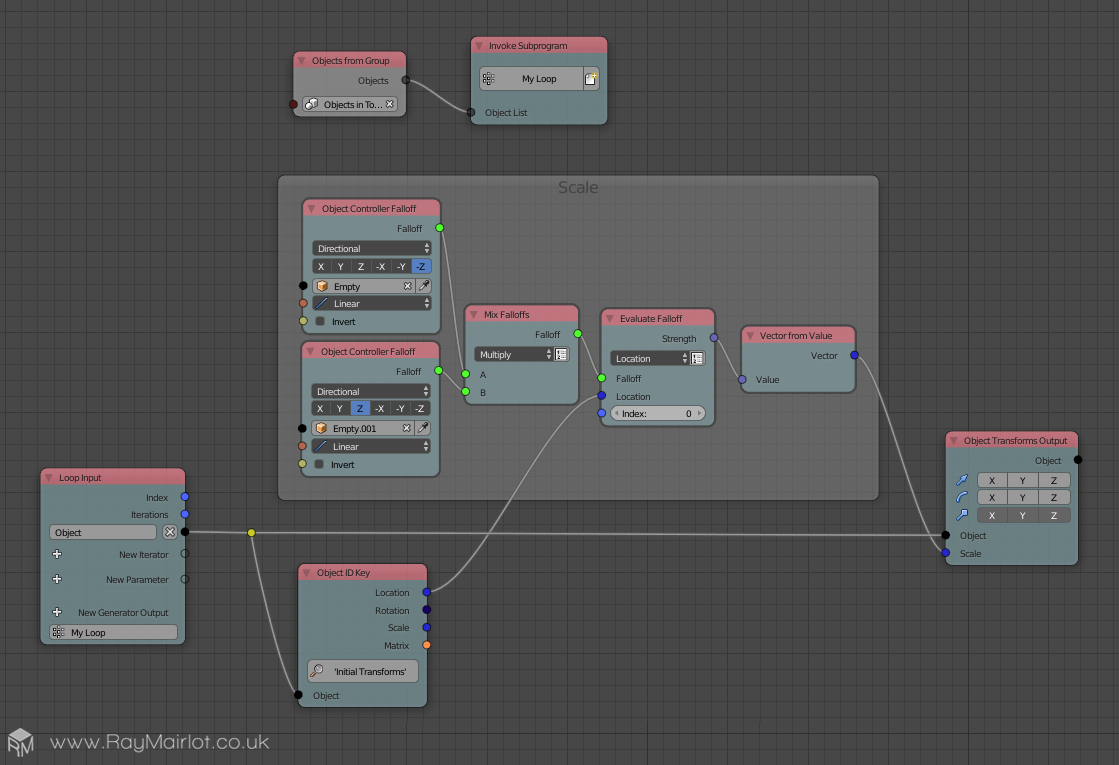
Now we've calculated the location and the scale we can add all the nodes together, producing this wonder:
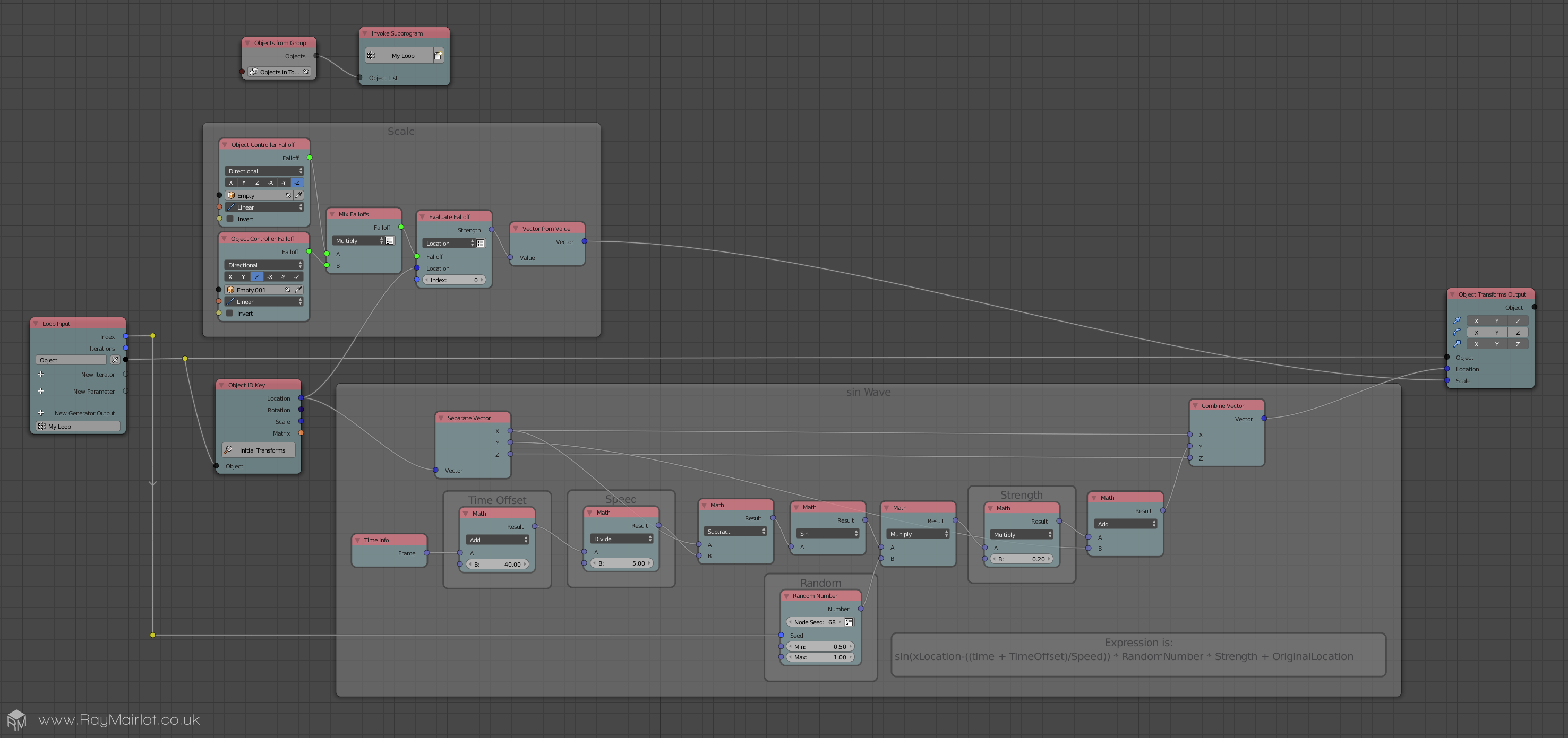
Look at that big, lovely, seamless screenshot. It's almost as if I used some automated method to capture it...
Really, I should have added in a few more images, gifs or some other animated doodahs to break up those chunks of text, but golly gosh, I really couldn't be bothered; it took long enough just to write all of this without faffing about making nice illustrative, understandable and helpful images.
So there we have it, a completely clear, 100% explained, nothing vague, detailed, step-by-step guide of how I did it. Apart from all the parts I skimmed over and left to you, the avid reader, to figure out for yourselves. Which, in fairness to me - and I have been assured that I definitely deserve fairness - is only really the animating of the empties and the adding and connecting of the nodes.
Well done me. And well done to you for getting this far. But mainly well done me. Because let's be honest, it's me that's done most of the work in this transaction. I've had to use all 10 fingers to type, you've just had to use two eyes. Or whatever number of eyes you have available to you. Either way, regardless of the number of operational eyes, 10 fingers is more. No one's got 10 eyes...
...Unless you're reading it in a group.
Bugger.
Ray.